

| Attribute | Value |
|---|---|
| Product Category: | |
| Manufacturer: | TE Connectivity |
| Manufacturer Part Number: | TE Connectivity 5-103735-8 |
| Series: | AMPMODU MTE |
| Amperage: | 3 A |
| Housing Material: | Thermoplastic |
| Number of Contacts: | 9 |
| Number of Rows: | 1 |
| Termination Method: | Crimp, Insulation Displacement Crimp (IDC), Through Hole - Solder |
| Contact Material: | Brass |
| Pitch: | .1 in, 2.54 mm |
| Contact Type: | Pin |
| Strain Relief: | No Strain Relief |
| Row Spacing: | .1 in, 2.54 mm |
| Package Quantity: | 21 |
| Contact Amperage: | 3 A |
| Number of Positions: | 9 |
| Housing Color: | Black |
| Mount Orientation: | Vertical |
| Insulation Resistance: | 5000 MΩ |
| GPL: | 296 |
| Packaging: | Tube, Tube/Box |
| Operating Temperature Range: | -65 - 105 °C |
| Circuit Application: | Signal |
| Contact Mating Area Plating: | Gold |
| Contact Mating Area Plating Thickness: | 30 µin |
| PCB Retention: | Without |
| PCB Contact Termination Area Plating: | Tin |
| Connector Height: | 13.59 mm, .535 in |
| GPL Description: | Industrial |
| Connector and Contact Terminate To: | Printed Circuit Board |
| Product Code: | 5465 |
| Connector Length: | 1 in, 25.4 mm |
| ECCN: | EAR99 |
| Dielectric Withstanding Voltage: | 600 V |
| Termination Resistance: | 15 mΩ |
| Contact Shape: | Square |
| PCB Contact Termination Area Plating Finish: | Matte |
| Mating Retention: | With |
| PCB Mount Alignment: | Without |
| Termination Post Tail Length: | .13 in, 3.3 mm |
| Header Type: | Shrouded |
| Connector Assembly Type: | PCB Mount Header |
| PCB Contact Termination Area Plating Thickness: | 100 µin, 2.54 µm |
| Contact Mating Area Length: | .23 in, 5.84 mm |
| Contact Retention: | With |
| Contact Retention Type in Housing: | Locking Lance |
| Standards Met: | CSA LR7189 UL E28476 |
| Material Flammability Standard: | UL 94V-0 |
| Part Aliases: | 5-103735-8 |
| SKU: | AMP5-103735-8 |
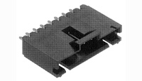
5-103735-8
Specifications
Detailed Description
Introducing the AMPMODU MTE series PCB Pin Header, a high-performance connectivity solution for your PCB assembly needs. This black housing header features 9 gold-plated brass contacts, each with a current rating of 3A. With a pitch of 2.54mm (.1 in) and vertical mount orientation, it offers versatility in installation. CSA and UL certified, this header ensures reliable performance in industrial environments with an operating temperature range of -65 to 105°C. Its crimp, through-hole, or IDC termination options provide flexibility in assembly, while the 600V dielectric withstanding voltage guarantees safety. RoHS compliant and packaged in tubes, the AMPMODU MTE header is ideal for signal applications in various electronic systems.
For Use With
| Product | Part # | Description | Stock |
|---|---|---|---|
 | TE Connectivity 103648-8 |  | |
 | TE Connectivity 5-103958-8 | | |
 | TE Connectivity 5-103961-8 | |
Product Change Notice
| Effective Date | Description of Change | Download | |||
|---|---|---|---|---|---|
| 05/29/2020 | E-20-000624 - Product Improvement. To provide flexibility to our manufacturing processes, we are allowing the manufacturing plants, when possible, to utilize regrind resin, up to the allowable limit specified on the UL Yellow Card, in the molding process. Adding feature at latch to increase mold efficiency. | Download | |||
| 04/25/2019 | P-19-016981 - Manufacturing Location Change. We hereby inform you about a transfer of tools and/or processes. | Download | |||
| 04/25/2019 | P-19-016996 - Manufacturing Location Change. The manufacturing location will change from TE's outside vendor in China to our TE plant in Hermosillo, Mexico. | Download | |||
| 03/31/2017 | E-16-014615 - Product Improvement. To satisfy customer demand for the capability of MTE headers to handle RoHS solder temperatures, TE Connectivity has retooled the MTE header product line to use high temperature compatible LCP molding material. These changes will result in the following product changes: 1) Housing material will change from high temperature nylon to LCP. 2) The header housing width will be reduced by 0.005 inches to accommodate the assembly process. 3) In order to consolidate some housing features, the contact cavity configuration will be changed slightly as shown in the attached sketch. | Download | |||
Availability
In Stock:
Call
Stock Location:
In Stock
Factory Stock:
Call for Stock
Factory Lead:
Call
Unit Of Measure:
Each
Minimum/Multiple:
1/1
Invalid quantity value

Documents & Media
Environmental & Export Classifications
| Attribute | Value |
|---|---|
| RoHS Compliant: | Unkown |